DIY Arduino Heat Bed for 3D Printer
Standalone Arduino-controlled heat bed system for upgrading obsolete 3D printers. Features temperature control, safety monitoring, and modular design for retrofitting older printer models without built-in heated beds.
Overview
My 2017 Sindoh DP201 3D printer didn’t have a heated bed, which meant large prints would warp and detach from the build plate as they cooled. After two years of failed prints, I built an Arduino-based temperature control system to retrofit a heated bed onto the printer. The most interesting part wasn’t the heating element itself—it was the automated control system: a light sensor detects when the printer’s LED turns on during a print job, automatically activates the heated bed, and maintains target temperature using proportional control. When the print finishes and the light turns off, the bed cools down. No manual switches, no wasted electricity heating an empty bed. View source code →

Automated Print Detection
The clever part was using a light sensor for fully automated operation. I configured the printer to turn on its LED only during active prints, then positioned the light sensor next to the lamp. When ambient light exceeds a threshold (around 70%), the controller knows a print is running and activates the heated bed. When the print finishes, the light turns off and the bed automatically cools down. This eliminated the need for any manual intervention—just start your print and the system handles the rest.
Temperature Control Algorithm
The controller implements a simple but effective three-zone control strategy: below 60°C it heats at full power (100% PWM), above 80°C it shuts off completely, and in the 60-80°C range it uses proportional control. The proportional zone calculates PWM duty cycle as a linear function of current temperature, preventing overshoot while maintaining stable temperature during long prints. A thermistor provides continuous feedback, sampled 5 times and averaged every half second to filter out noise.
Components
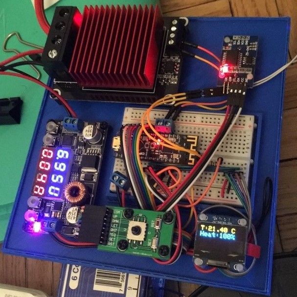
The build uses an Arduino Nano, MK2B heated bed with thermistor, 5V-compatible MOSFET module for high-current switching, photoresistor light sensor, 128x64 OLED display, and 12V power supply. The critical component choice was the MOSFET—many modules require 6.4V+ gate voltage, but Arduino PWM outputs are only 5V. I used a UEETEK module specifically designed for 5V logic, allowing direct PWM control from the Arduino without level shifters.
Build Gallery
Finished control board in custom 3D-printed enclosure (CAD files)
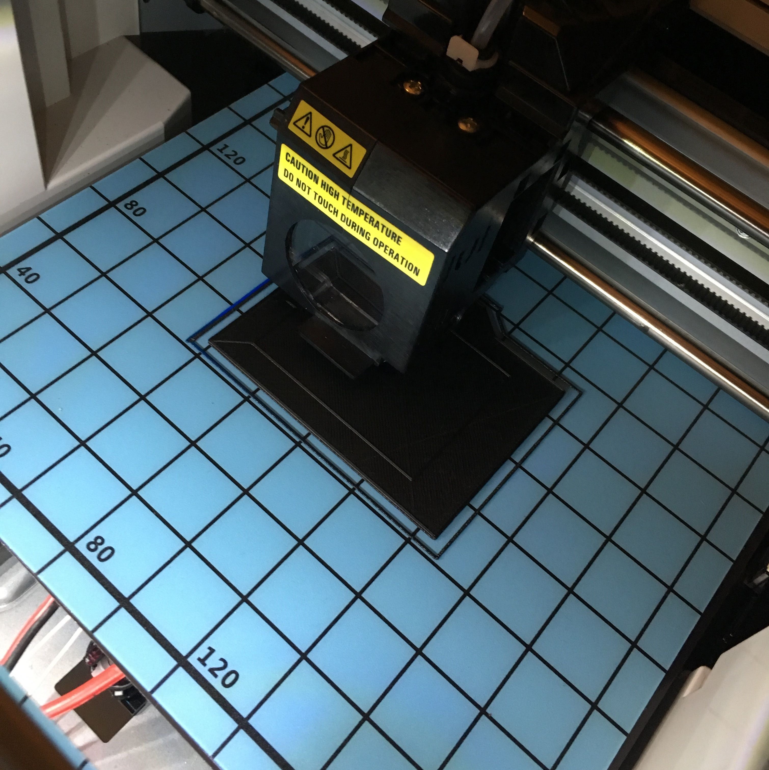
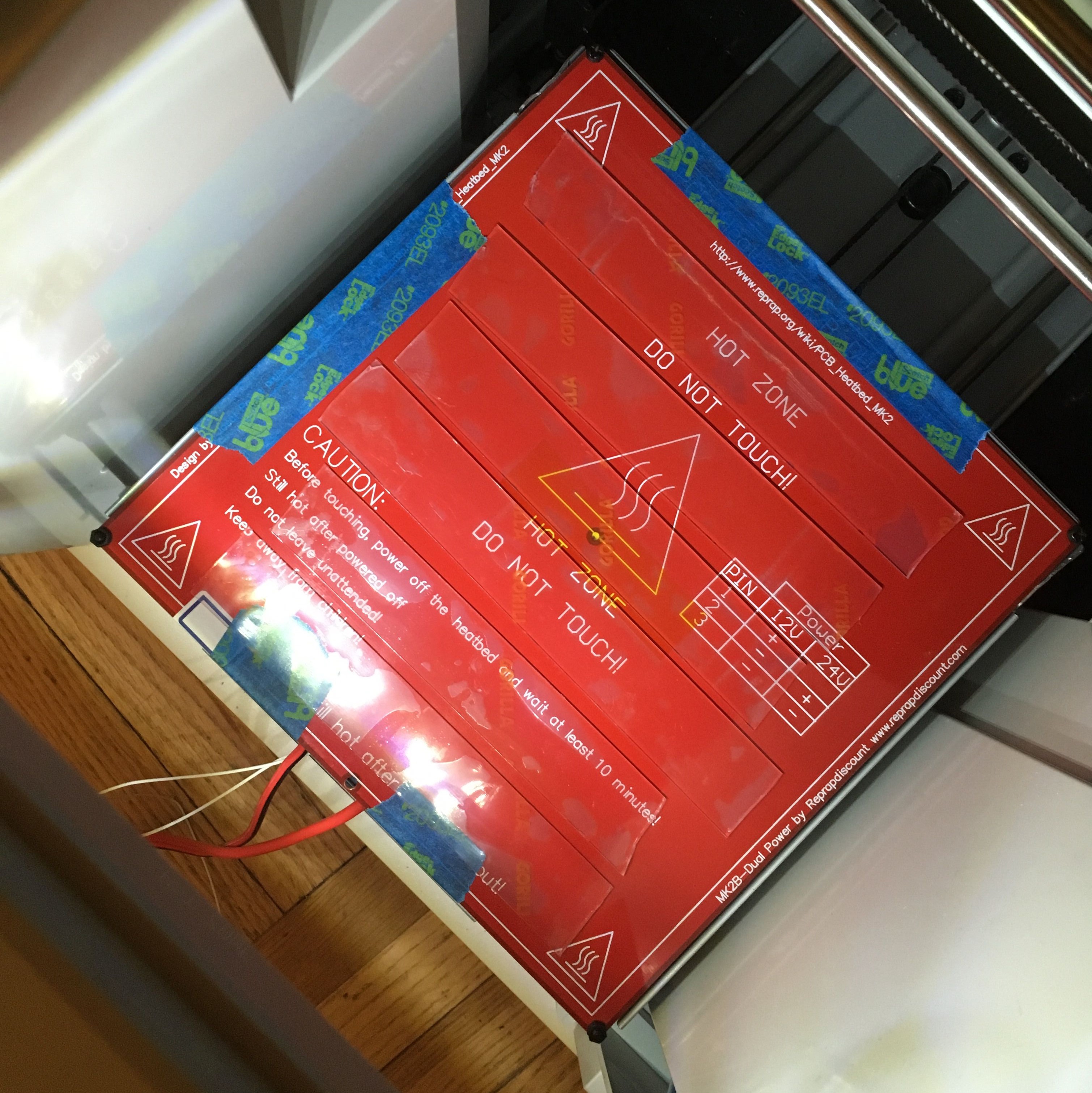 Heated bed mounted to build plate
Magnetic build surface installed
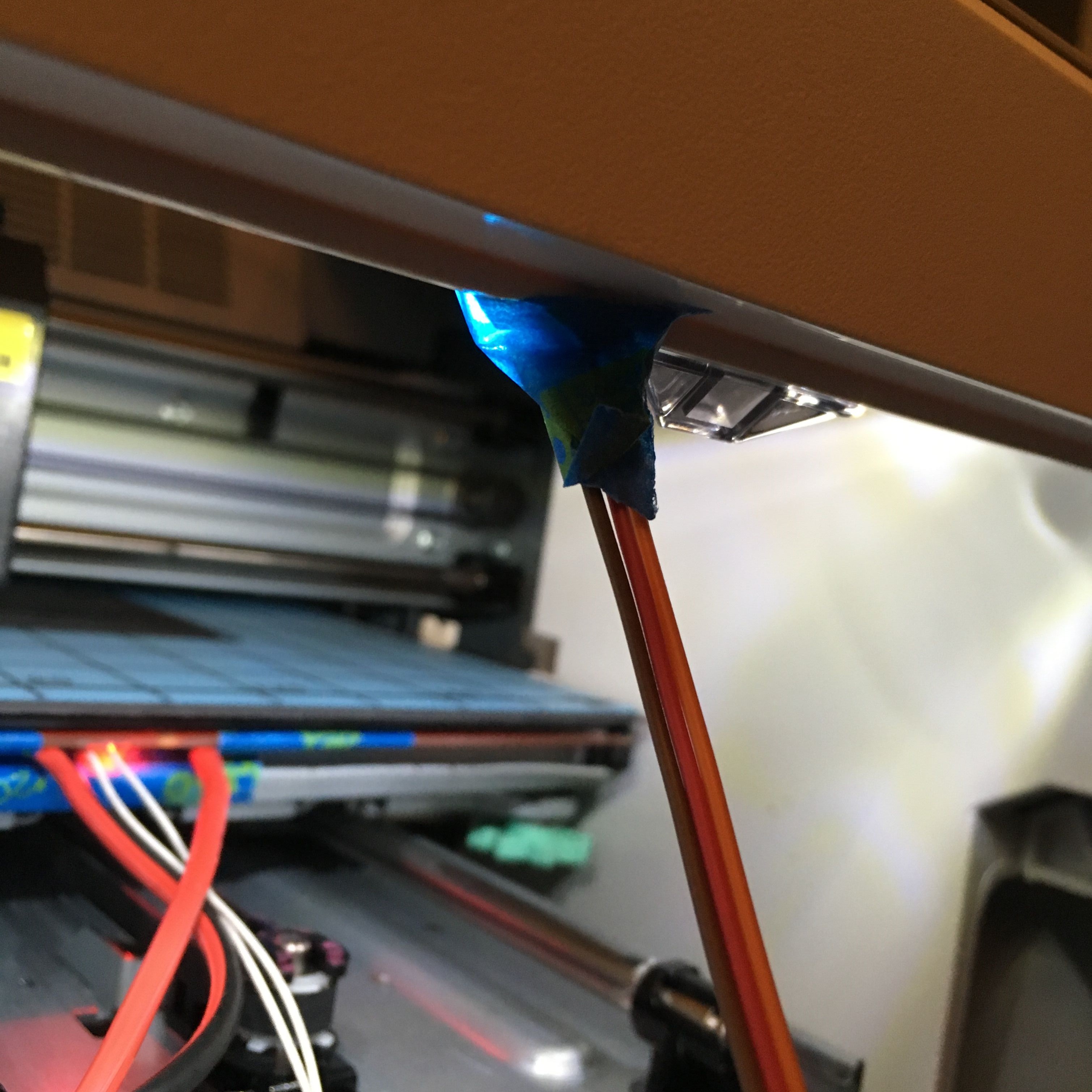 Light sensor positioned next to printer LED for automated print detection
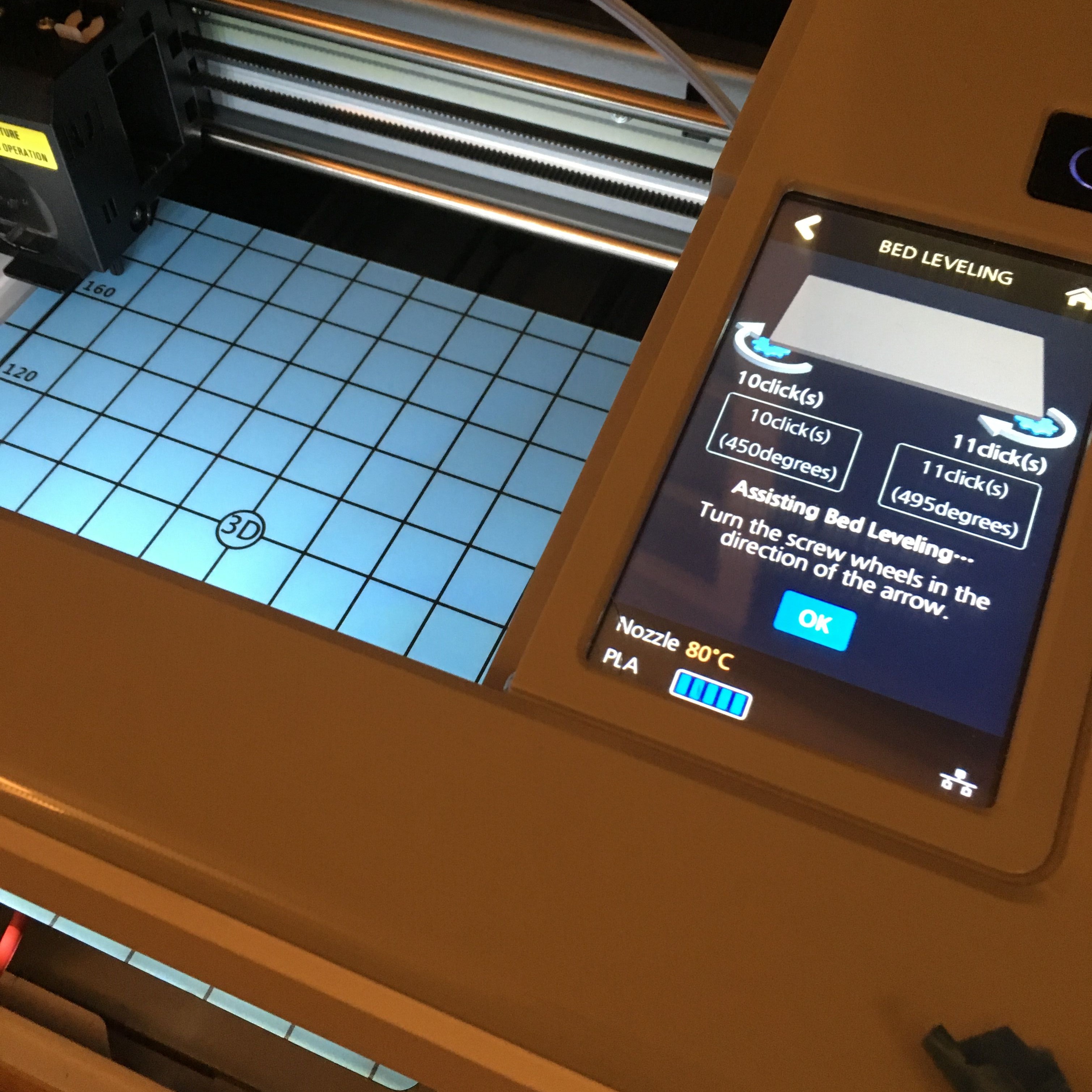 Z-offset calibration after installation
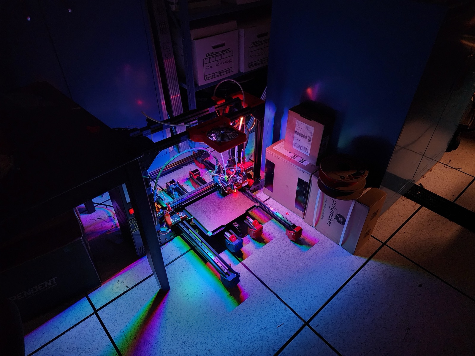
Large print with no warping
Code
The implementation shows the core control logic: tempRead() samples the thermistor 5 times and averages using the Steinhart-Hart equation for accurate temperature conversion. mosfetControl() implements the three-zone heating strategy. isLightOn() reads the photoresistor and triggers heating when light exceeds 70% threshold. The main loop runs this control cycle twice per second.
#include <Adafruit_GFX.h>
#include <gfxfont.h>

#define NUMSAMPLES 5
#define mosPin 3
#define lightPin 3
#define thermistorPin 7

#define minTemp 60
#define maxTemp 80

#include <SPI.h>
#include <Wire.h>
#include <Adafruit_GFX.h>
#include <Adafruit_SSD1306.h>

#define OLED_RESET 4
Adafruit_SSD1306 display(OLED_RESET);

#define NUMFLAKES 10
#define XPOS 0
#define YPOS 1
#define DELTAY 2


#define LOGO16_GLCD_HEIGHT 16
#define LOGO16_GLCD_WIDTH  16
static const unsigned char PROGMEM logo16_glcd_bmp[] =
{ B00000000, B11000000,
  B00000001, B11000000,
  B00000001, B11000000,
  B00000011, B11100000,
  B11110011, B11100000,
  B11111110, B11111000,
  B01111110, B11111111,
  B00110011, B10011111,
  B00011111, B11111100,
  B00001101, B01110000,
  B00011011, B10100000,
  B00111111, B11100000,
  B00111111, B11110000,
  B01111100, B11110000,
  B01110000, B01110000,
  B00000000, B00110000 };

#if (SSD1306_LCDHEIGHT != 64)
#error("Height incorrect, please fix Adafruit_SSD1306.h!");
#endif


int samples[NUMSAMPLES];

int Vo;
float R1 = 100000;
float logR2, R2, T, Tc, Tf;
float c1 = 0.7203283552e-3, c2 = 2.171656865e-4, c3 = 0.8706070062e-7;

void setup() {
Serial.begin(9600);
pinMode(mosPin, OUTPUT);
// by default, we'll generate the high voltage from the 3.3v line internally! (neat!)
  display.begin(SSD1306_SWITCHCAPVCC, 0x3C);  // initialize with the I2C addr 0x3D (for the 128x64)
  // init done

  // Show image buffer on the display hardware.
  // Since the buffer is intialized with an Adafruit splashscreen
  // internally, this will display the splashscreen.
  display.display();
  delay(1000);

  // Clear the buffer.
  display.clearDisplay();
}

void tempRead(){
  uint8_t i;
  float average;

  for (i=0; i< NUMSAMPLES; i++) {
    samples[i] = analogRead(thermistorPin);
    R2 = R1 * (1023.0 / (float)samples[i] - 1.0);
    logR2 = log(R2);
    T = (1.0 / (c1 + c2*logR2 + c3*logR2*logR2*logR2));
    samples[i] = T - 273.15;
    delay(10);
  }
  average = 0;
  for (i=0; i< NUMSAMPLES; i++) {
     average += samples[i];
  }
  average /= NUMSAMPLES;
  Tc = average;
//  Serial.print(Tc);
//  Serial.print(" C ");

  display.setTextSize(2);
  display.setTextColor(WHITE);
  display.setCursor(0,0);
  display.print("T:");
  display.print(Tc);
  display.println(" C");
}

void turnOnHeat(){
  analogWrite(mosPin, 255);
}

void turnOffHeat(){
  analogWrite(mosPin, 0);
}

void turnHeatNum(int num){
  analogWrite(mosPin,int(num));
}

void mosfetControl(bool on){
  display.print("Heat:");
  if (Tc < minTemp && on){
    turnOnHeat();
    display.println("100%");
  }
  else if (!on || Tc > maxTemp ){
    turnOffHeat();
    display.println("0%");
  }
  else {
    int num;
    num = int(-(255/(maxTemp-minTemp))*(Tc-minTemp)+255);
    Serial.println(num);
    turnHeatNum(num);
    display.print(int(num*100/255));
    display.println("%");
  }
}

bool isLightOn(){
  float sensitivity = 700;
  float lightRead;
  lightRead = analogRead(lightPin);
  display.print("L:");
  display.print(lightRead/1023*100);
  display.println("%");
  if (lightRead > sensitivity){
    return true;
  }
  return false;
}

void loop() {
  tempRead();
  if (isLightOn()){
    mosfetControl(1);
  }
  else {
    mosfetControl(0);
  }

  display.display();
  delay(500);
  display.clearDisplay();
}
Discover more...
The Pipeline: Automating 3D Printing at Scale
Hacking Graduation Embroidery with 3D Printing